
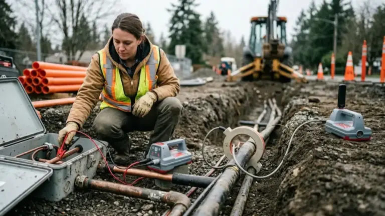
A transmitter can put an active locating signal on a utility in three main ways: direct connection, clamp induction, and broadcast induction. A radio detection transmitter may support all three methods, but each method creates a different signal path.
Direct connection usually gives you the strongest and most selective signal. A clamp works well when you can reach the conductor but cannot make direct electrical contact. Broadcast induction works without physical access, but it gives you less control over which line carries the signal.
That order matters in a congested utility corridor.
This comparison uses manufacturer documentation, industry guidance, and federal safety requirements. It does not present invented field measurements or claim that one method always wins.
The Short Answer
Use direct connection first when you can safely reach the correct conductor.
Use a compatible transmitter clamp when you can surround the conductor but cannot connect directly.
Use broadcast induction when you cannot reach or surround the target, or when you need to sweep an area for unknown conductive utilities.
| Method | Best use | Main advantage | Main limitation |
| Direct connection | Known utility with an accessible connection point | Strong signal and good target selectivity | Requires safe electrical contact and a return path |
| Transmitter clamp | Accessible insulated cable or conductor | Applies a focused signal without direct contact | Requires the correct clamp and a usable signal loop |
| Broadcast induction | Inaccessible or unknown conductive utility | Requires no physical connection | Can energize several nearby conductors |
This ranking describes signal application. It does not guarantee that the receiver has identified the correct utility.
How an Active Locate Works
A transmitter creates an alternating current at a selected frequency. The current travels along a conductive pipe, cable, sheath, or tracer wire. That current produces a magnetic field around the conductor.
The receiver detects the magnetic field. It does not detect the physical pipe or cable itself.
This distinction explains many difficult locates. A receiver can follow a strong field on the wrong conductor when the signal transfers through a shared ground, a bond, or electromagnetic coupling. Nearby lines can also distort the field and move its apparent peak away from the actual target.
The signal application method controls how much current reaches the target and how easily that current transfers to other conductors.
Direct Connection
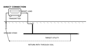
Direct connection forms an electrical circuit between the transmitter, the target conductor, and the return ground.
The operator connects one transmitter lead to an approved access point. Common access points include a tracer wire, valve, meter, test station, cable sheath, or another exposed conductive part. The second lead connects to a ground stake or another approved return point.
The signal then travels along the utility and returns through the ground circuit.
Radiodetection states that signal range depends on the line type, conductor size, soil conditions, insulated joints, and selected frequency. Lines that share a common ground can also carry part of the applied signal.
Why Direct Connection Usually Works Best
Direct connection puts the transmitter output into a defined circuit. The operator controls the connection point, ground position, frequency, and output level.
That control normally produces three benefits:
- More current reaches the target.
- Less signal reaches unrelated conductors.
- The operator can use a wider range of frequencies.
A clean direct connection also helps with long traces. Low frequencies usually travel farther and transfer less readily to nearby conductors. However, they need a continuous conductor and a good return path.
Direct connection still fails when the circuit is poor. More transmitter power does not fix a broken tracer wire, insulated joint, bad contact point, or ineffective ground stake.
Contact Quality Matters
Paint, rust, dirt, and corrosion can restrict current at the connection point. A damaged lead can create the same symptom.
The transmitter may show low current or high resistance. The receiver may produce a weak response that disappears a short distance from the connection point.
The operator should first inspect the connection and ground circuit. Increasing frequency should come later.
A higher frequency may cross some resistive sections or insulated joints through capacitive coupling. It may also move onto nearby lines more easily.
The Ground Stake Can Change the Locate
The ground stake does more than complete the circuit. Its position affects where the return current travels.
Place the stake away from the target and other buried utilities. Run the ground lead away from the expected utility route rather than parallel to it.
A stake beside another utility may put signal onto that utility. A fence, cabinet, common grounding bar, or other convenient metal structure can create an even larger unwanted circuit.
Dry or resistive soil can also weaken the ground connection. The correct response depends on the equipment manual, site conditions, and applicable electrical procedures.
Common Grounds Create False Confidence
A strong receiver response does not prove that the signal stayed on the connected line.
Several utilities may share a grounding point at a building, transformer, pedestal, or service entrance. The applied current can split between them.
One adjacent line may even produce a stronger receiver response because it sits closer to the surface. Signal strength changes with depth as well as current.
Current measurement can help on receivers that support it. The conductor carrying the highest calculated current may differ from the conductor producing the strongest raw response. Current measurement still depends on a clean field and a reliable depth estimate.
Transmitter Clamp
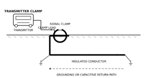
A transmitter clamp applies the signal through transformer action.
The split magnetic core closes around the target conductor. The transmitter energizes a winding inside the clamp. The encircled conductor acts as the secondary winding and carries the locating current.
The clamp does not need exposed metal-to-metal contact. It also does not need a separate ground lead from the transmitter.
When a Clamp Makes Sense
A clamp works well when the target is accessible but a direct connection is unsafe or impractical.
Typical examples include:
- An insulated power cable.
- A telecom cable inside a pedestal.
- A conductor that cannot be disconnected.
- A cable with no approved direct connection point.
- A group of cables where the operator can isolate one conductor physically.
The clamp focuses more energy on the conductor inside its jaws than broadcast induction would apply from the surface.
It can also reduce signal transfer to nearby utilities. It cannot eliminate that transfer completely.
The Conductor Still Needs a Circuit
A clamp does not remove the need for a return path.
The target normally needs a ground connection or sufficient capacitive coupling on both sides of the clamp. A long buried insulated cable may provide enough coupling through the surrounding soil. A short isolated conductor may not.
The operator should not assume that every accessible cable can carry a clamp-applied signal.
A two-conductor circuit can create another problem. Both conductors may carry similar signal levels because the current travels out on one conductor and returns on the other. A strong response then does not identify one conductor conclusively.
Jaw Closure Controls Signal Transfer
The clamp jaws must close completely.
Dirt, damage, cable tension, or poor positioning can leave a small gap in the magnetic core. That gap can reduce signal transfer sharply.
The operator should inspect:
- Both mating surfaces.
- Spring pressure.
- Jaw alignment.
- Cable insulation.
- Connector condition.
- Strain relief.
The clamp should surround only the intended conductor. A clamp around a common ground bar may send most of the signal directly into the grounding network.
Clamp Size Does Not Prove Compatibility
A clamp that fits around a cable may still be incompatible with the transmitter.
Compatibility depends on:
- Connector type.
- Internal winding.
- Frequency range.
- Transmitter generation.
- Accessory detection.
- Current Direction or other special functions.
- Manufacturer requirements.
Radiodetection states that its standard transmitter clamps support frequencies from 8 kHz to 200 kHz. Its standard clamp accepts conductors up to 5.25 inches (130 mm), while its small clamp accepts conductors up to 50 mm. Radiodetection also distinguishes transmitter clamps from receiver clamps because they use different windings and plug orientations.
Those specifications apply to the named Radiodetection accessories. They do not define compatibility for clamps from Subsite, Vivax-Metrotech, or another manufacturer.
Always confirm the exact transmitter model, clamp model, connector, and frequency range.
Clamp Safety Around Power Cables
A transmitter clamp can apply a signal to some live insulated cables without interrupting service. That does not make every clamping procedure safe.
Radiodetection warns operators not to clamp around uninsulated live conductors. It also instructs operators to connect the clamp to the transmitter before applying or removing it around a power cable.
The operator must follow the manual for the exact clamp and transmitter. Utility-owner procedures and electrical qualifications still apply.
Broadcast Induction
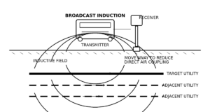
Broadcast induction uses the transmitter’s internal coil. The operator places the transmitter on the ground above the expected utility route.
The coil creates a magnetic field below and around the transmitter. A conductive line inside that field receives an induced voltage. Current then flows when the line has a usable return path.
No direct access is required.
That convenience comes with less control.
Alignment Controls the Result
The transmitter must align with the target conductor.
A line running parallel to the transmitter coil receives stronger coupling. A line crossing the coil at the wrong angle may receive little signal.
The operator can rotate or move the transmitter to change which conductors receive energy. This technique helps during a sweep, but it does not guarantee isolation in a congested corridor.
Radiodetection states that induced current depends on the line’s grounding, the selected frequency, and the presence of insulated joints.
Induction Can Energize Several Lines
The transmitter field does not stop at the target.
Nearby pipes, cables, fences, rails, and other conductors may also receive the signal. The line with the best grounding can carry the strongest current, even when it is not the intended target.
Higher frequencies make induction easier. They also increase coupling to adjacent conductors.
Radiodetection describes induction as less effective than direct connection or clamping. It also notes that line identity often remains uncertain when several conductors lie inside the transmitter field.
This makes induction useful for detection but weaker for identification.
Air Coupling Can Mimic a Utility Signal
The receiver can detect the transmitter’s field directly through the air.
This usually creates a strong response near the transmitter. The response may disappear when the receiver moves farther away because no buried conductor carries enough current.
The operator must maintain sufficient distance between the transmitter and receiver. The correct distance depends on the equipment, frequency, power, and task.
Radiodetection instructs operators to place an inductive transmitter at least 50 feet (15 m) from a depth-measurement point when direct connection or clamping is unavailable.
That figure applies to the cited Radiodetection procedure. Other equipment manuals may specify a different distance.
Induction Works Well for Active Sweeps
Broadcast induction can help find unknown conductive utilities across a work area.
A two-person sweep works better than a stationary guess. One operator carries the transmitter in a controlled path. The second operator follows at the required distance with the receiver.
The crew can repeat the sweep from another direction. A conductor that crosses the search path may show a clear response.
The response confirms a conductive signal path. It does not confirm utility ownership, service type, or exact identity.
Signal Strength Is Not the Same as Selectivity
A strong signal feels reassuring. It can still lead to the wrong line.
Direct connection normally produces the strongest target current. A correctly selected clamp usually comes next. Broadcast induction generally produces less target current.
The ranking can change under poor conditions.
A clamp may outperform a direct connection when the direct contact is corroded or the ground circuit is weak. Induction may produce a strong response on a nearby well-grounded cable while barely energizing the intended pipe.
The operator should evaluate signal quality, not just signal level.
Useful checks include:
- Does the route match known access points?
- Does the signal continue past a known structure?
- Does current fall gradually or change suddenly?
- Do Peak and Null positions agree?
- Does the line remain consistent after a frequency change?
- Does another application method produce the same route?
- Can the crew trace the line to a confirmed termination?
One reading rarely answers every question.
Frequency Changes the Circuit
Frequency controls how easily the signal stays on the target, crosses resistive sections, and transfers to adjacent conductors.
Lower Frequencies
Lower frequencies usually:
- Travel farther on a continuous conductor.
- Produce less unwanted coupling.
- Give better target discrimination.
- Need a good electrical circuit.
They work best with direct connection. Some specialized clamps also support lower frequencies, but standard clamp ranges differ by manufacturer.
A low frequency may fail on a short, poorly grounded, or discontinuous target.
Medium Frequencies
Frequencies around 8 kHz to 33 kHz often provide a practical balance.
They support direct connection, many standard clamps, and broadcast induction on common locating systems. They also couple more readily than very low frequencies.
This range works for many general locating tasks. It is not universally correct.
Higher Frequencies
Higher frequencies can help when:
- The target has high resistance.
- The ground circuit is weak.
- Insulated joints interrupt direct current flow.
- Broadcast induction produces no useful response.
The same frequency can also energize nearby conductors, fences, and grounded structures.
Start with the lowest supported frequency that produces a stable trace. Move higher only when the circuit requires it.
More Power Can Make the Locate Worse
More transmitter output increases the available signal. It also increases the chance of coupling.
The operator should not begin every locate at maximum power.
First check:
- The direct connection point.
- The ground stake.
- The clamp closure.
- The selected frequency.
- The transmitter alignment.
- The target’s return path.
- The receiver’s distance from the transmitter.
Increase output only after the physical setup checks out.
Use enough power to trace the target. Don’t flood the entire corridor.
Field Comparison by Scenario
| Field condition | Recommended starting method | Reason |
| Accessible tracer wire with confirmed continuity | Direct connection | Strong and selective circuit |
| Accessible insulated cable with no approved contact point | Compatible clamp | Focused signal without direct contact |
| Unknown utility with no access point | Broadcast induction | Supports an active sweep |
| Congested parallel utility corridor | Low-frequency direct connection | Reduces unwanted coupling |
| Cable group inside a pedestal | Small compatible clamp | Isolates one accessible conductor |
| Long continuous metallic line | Low-frequency direct connection | Supports longer signal travel |
| Poorly grounded or discontinuous line | Higher supported frequency after circuit checks | Improves coupling across resistance |
| Critical depth measurement | Direct connection or clamp | Reduces induction-related distortion |
| HDD crossing | Physical exposure after locating | Receiver depth alone does not verify clearance |
No method replaces verification.
How to Confirm the Correct Utility
Target identification needs several matching pieces of evidence.
Trace the Line to Known Features
Follow the signal toward a known valve, meter, pedestal, test station, riser, or termination.
A route that does not connect with the expected utility layout needs further investigation.
Records can also contain errors. Use them as evidence, not proof.
Compare Peak and Null Positions
A clean field should place the Peak and Null responses close together on receivers that support both modes.
A separation between them indicates field distortion. Nearby conductors, bends, tees, or coupled signals can cause that distortion.
Move to a straighter section and repeat the check.
Compare Current Along the Route
Current should usually change gradually on a continuous conductor.
A sudden change can indicate:
- A branch.
- A bond.
- A grounding point.
- Signal transfer.
- A damaged tracer.
- A change in line conditions.
Current measurement supports identification. It does not replace route logic or physical verification.
Change the Application Method
A route that remains consistent under two controlled application methods has stronger support.
For example, connect directly at one access point, then apply a clamp at another accessible section. Compare the route, current, field shape, and depth estimates.
Broadcast induction can provide another check, but it carries a greater risk of energizing adjacent conductors.
Change the Frequency
A target that disappears when the operator moves to a lower frequency may have poor continuity or weak grounding.
An adjacent coupled conductor may also lose signal faster than the connected target.
Frequency response adds evidence. It does not create an automatic identification test.
Depth Readings Need a Clean Field
A receiver estimates depth from the detected magnetic field.
The reading can shift when:
- Another line carries part of the signal.
- The target bends or branches.
- The field becomes distorted.
- The receiver sits inside the transmitter’s induction field.
- The operator tilts the receiver.
- Electromagnetic interference changes the response.
Radiodetection states that depth accuracy depends on the target, depth, ground conditions, electromagnetic noise, and interference. It also warns operators not to use locator depth to define mechanical digging depth.
Use depth as a locating measurement.
Do not use it as exposure.
Safety Comes Before Signal Quality
The crew must complete the applicable one-call process before excavation or drilling. The crew must also review records, surface evidence, private utility information, and known access points.
OSHA requires employers to determine estimated utility locations before opening an excavation. When excavation approaches an estimated location, the employer must determine the exact location through safe and acceptable means.
The transmitter does not replace that process.
Direct connections to energized systems require the correct approved accessory and qualified personnel. A transmitter’s protection circuit does not make an unsafe connection acceptable.
A clamp also needs model-specific safety checks. Never assume that a clamp designed for one system, voltage condition, or conductor type applies to another.
For an HDD crossing, physically expose the utility where required. Confirm its horizontal position, actual depth, material, diameter, and clearance.
Buying a Clamp for an Existing Transmitter
A clamp can improve crew flexibility. The wrong clamp can sit unused in the case.
Before buying, confirm:
- Exact transmitter manufacturer and model.
- Hardware generation.
- Connector type.
- Supported frequencies.
- Maximum jaw opening.
- Standard or low-frequency winding.
- Current Direction or Signal Select functions.
- OEM or aftermarket status.
- Cable length and insulation condition.
- Warranty and return terms.
Used clamps need closer inspection. Check the jaws, mating faces, spring pressure, cable, strain relief, plug, and part number.
Test the clamp with the intended transmitter before relying on it in the field.
Physical fit is not electrical compatibility.
Which Method Should You Use?
Choose the method that gives you the best-controlled signal under the actual site conditions.
Direct connection should remain the first choice when safe access exists. It gives you the strongest control over the circuit, frequency, and output.
A compatible clamp should come next. It works well on accessible insulated conductors and reduces the need for direct electrical contact.
Broadcast induction should fill the access gap. It supports active sweeps and inaccessible targets, but it requires more verification in congested areas.
The method only starts the locate.
The crew still needs to check the route, field shape, current, frequency response, known structures, and physical exposure. That final verification matters more than a strong number on the receiver screen.